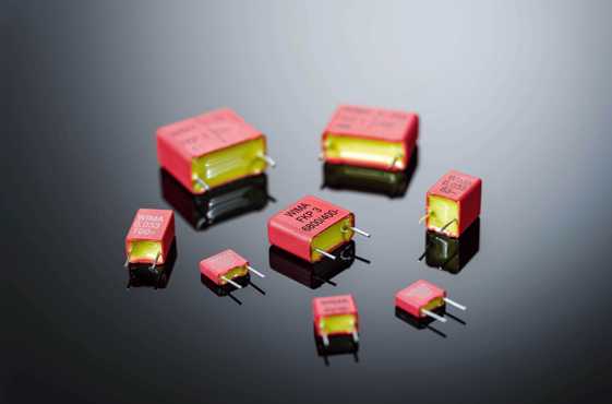
Film/foil capacitors

In the case of film and foil types, the electrode is not applied as for the metallized capacitors, but is wound with the dielectric as a metal foil. Due to their lower series resistance, the components produced this way have excellent pulse and current carrying capability, as well as a very high insulation resistance.
The film/foil construction is mainly used for capacitors with smaller capacitance value. The advantage of this construction principle is the easy contactability of the metal foil electrodes and the good pulse strength. To avoid breakdowns caused by weak spots in the dielectric, the insulating film chosen is always thicker than theoretically required by the values which are determined from the specific breakdown strength of the material.
WIMA film/foil capacitors in PCM 5 mm to 15 mm are available in two dielectric versions. WIMA capacitors with a Polyester dielectric (PET) are suitable for general applications such as coupling, decoupling and by-passing. Polypropylene capacitors (PP) are used in the high frequency field. This includes resonant circuits, power supplies, deflection circuits, oscillator circuits and audio equipment.
WIMA film/foil capacitors in PCM 5 mm to 15 mm are available with capacitance values from 33 pF to 0.22 µF and rated voltages from 63 VDC to 1000 VDC.
| PCM 5 - 15 mm | |||||||||||||||||||||||
| film/foil | |||||||||||||||||||||||
FKS 2 |
FKP 2 |
FKS 3 |
FKP 3 |
||||||||||||||||||||
| Dielectric | Polyester film | Polypropylene film | Poyester film | Polypropylene film | |||||||||||||||||||
| Test category in accordance with IEC | 55/100/56 | 55/100/56 | 55/100/56 | 55/100/56 | |||||||||||||||||||
| Temperature range | -55°C to +105°C | -55°C to +100°C | -55°C to +105°C | -55°C to +105°C | |||||||||||||||||||
| Dissipat. factor tanδ at 1 kHz and +20°C | < 7 x 10⁻³ | < 5 x 10⁻⁴ | < 7 x 10⁻³ | < 5 x 10⁻⁴ | |||||||||||||||||||
| Insulation resistance at+20°C* | > 1 x 10⁵ MΩ | > 3 x 10⁵ MΩ | > 1 x 10⁵ MΩ | > 3 x 10⁵ MΩ | |||||||||||||||||||
| Voltage ranges VDC Capacitances |
63 | 100 | 250 | 400 | 630 | 63 | 100 | 250 | 400 | 630 | 800 | 1000 | 100 | 250 | 400 | 630 | 63 | 100 | 250 | 400 | 630 | 850 | 1000 |
| 27 pF | 5 | ||||||||||||||||||||||
| 33 pF | |||||||||||||||||||||||
| 47 pF | |||||||||||||||||||||||
| 68 pF | |||||||||||||||||||||||
| 100 pF | 5 | 5 | 5 | 5 | 5 | 5 | 7.5 | 7.5 | 7.5 | 7.5 | 7.5 | 7.5 | |||||||||||
| 150 pF | |||||||||||||||||||||||
| 220 pF | |||||||||||||||||||||||
| 330 pF | |||||||||||||||||||||||
| 470 pF | |||||||||||||||||||||||
| 680 pF | |||||||||||||||||||||||
| 1000 pF | 5 | 5 | 5 | 5 | 5 | 7.5 | 7.5 | 10 | 10 | ||||||||||||||
| 1500 pF | 10 | 10 | 10 | ||||||||||||||||||||
| 2200 pF | |||||||||||||||||||||||
| 3300 pF | 10 | 10 | |||||||||||||||||||||
| 4700 pF | |||||||||||||||||||||||
| 6800 pF | 15 | 15 | 15 | ||||||||||||||||||||
| 0.01 µF | 10 | 15 | |||||||||||||||||||||
| 0.015 µF | 15 | 7.5 | 10 | ||||||||||||||||||||
| 0.022 µF | 10 | 15 | |||||||||||||||||||||
| 0.033 µF | 10 | 15 | |||||||||||||||||||||
| 0.047 µF | 15 | 15 | |||||||||||||||||||||
| 0.068 µF | |||||||||||||||||||||||
| 0.1 µF | 15 | ||||||||||||||||||||||
| 0.15 µF | 15 | ||||||||||||||||||||||
| 0.22 µF | |||||||||||||||||||||||
| 0.33 µF | |||||||||||||||||||||||
| 0.47 µF | |||||||||||||||||||||||
| 0.68 µF | |||||||||||||||||||||||
| 1.0 µF | |||||||||||||||||||||||
| 1.5 µF | |||||||||||||||||||||||
| 2.2 µF | |||||||||||||||||||||||
| 3.3 µF | |||||||||||||||||||||||
| 4.7 µF | |||||||||||||||||||||||
| 6.8 µF | |||||||||||||||||||||||
| 10 µF | |||||||||||||||||||||||
| Capacitance tolerances | ±20%, ±10%, ±5% | ±20%, ±10%, ±5%, ±2.5% (±2%, ±1.5%, ±1%*) | ±20%, ±10%, ±5% | ±20%, ±10%, ±5% | |||||||||||||||||||
FKS 2 |
FKP 2 |
FKS 3 |
FKP 3 |
||||||||||||||||||||
* Available subject to special enquiry.
